I was a former owner of some planar magnetic loudspeakers which I had purchased through mail-order means, purchased strictly from their published specifications and reviews. I found out later this was my first mistake. As I began listening to them with a subwoofer to supplement their bass output, I realized there was a “hole” in the mid-bass response, due to the fact that this loudspeaker could not reproduce frequencies low enough to reach the upper limit of the subwoofer. Measurements confirmed what I had suspected, that they came nowhere close to meeting their published specifications in their bass response. This made me think of how they were constructed, with columns of magnets and a drum-like thin membrane stretched across the perimeter of the loudspeaker, spaced closely to the magnets, and with conductors running vertically adjacent to them. I knew there had to be or should be an alternate planar technology that would reproduce bass frequencies without the necessity of making the panels so large. But why a planar loudspeaker in the first place? To me, there has always been something alluring about the coherency of the large planar wavefront, although they also had other attributes I strongly disliked. In addition to their behemoth size necessary to produce bass, I’ve never cared much for the long line-source overblown presentation of voices in music, although for movie soundtracks this is more acceptable. I also never much liked the diffuse, somewhat softened sound they projected, along with the limited dynamics. Uh, what did I like about them again?
One night it occurred to me that this was nothing more than a simple motor, and I began thinking of a 4-H project I had submitted as a child for a 4-H fair. It was a simple DC electric motor, consisting of a two-pole armature fabricated from 16D nails and magnet wire. The motor stator was also an electromagnet, fashioned from many pieces of steel banding straps bent into a U-shape, then laminated and wound with magnet wire.
Figure 1 is representative of this simple DC electric motor, but the stator is comprised of permanent magnets instead of an electromagnet as I had constructed back then. Ordinarily, arc-segment magnets would also be used instead of block magnets, but this is just for illustrative purposes. Notice the direction of the flow of current, the layout of the magnets, and the resulting movement of the rotor, the armature. The left side of the armature will be moving toward you, the viewer, while the right side will be moving away from you, into the screen. But also note there is a split-ring commutator, along with brushes, to provide a reversal of the direction of current flow as it moves 180 degrees from its present position, thus continuing the rotation of the armature in relation to the stator.
Figure 1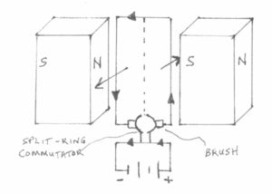
I was thinking about how sometimes when a battery was connected, if the armature wasn’t positioned just right in relation to the stator, it would start to move, but it wouldn’t have enough torque to continue moving a whole revolution, and so on, unless you gave it a starting push to provide the necessary momentum. After all, it was a crude two-pole motor, and the armature balance wasn’t the greatest either. I was thinking this could also represent a loudspeaker motor until I realized that the opposite armature pole would be moving backwards in relation to the first armature pole. Then I remembered that even if the opposite armature pole wasn’t even close to a stator magnet pole at all, it would still begin to move, just from the force exerted by the first armature pole in close proximity to its respective stator pole . It made me realize something which I just had to test experimentally: A current carrying conductor in close proximity to a single magnet pole will have a force exerted upon it. Sure, it seems so obvious now, a “duh” moment, but at the time it gave me further ideas. Yep, for one, I should get a life!
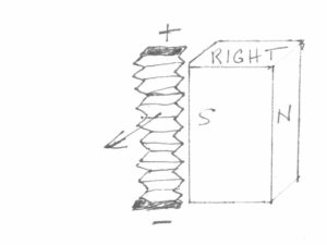
So what if you eliminated the other armature pole to create a ribbon or ribbon-like loudspeaker, with the fulcrum point being the location of the rotor shaft? Or as a natural extension to this idea, you could include both armature poles, but use a stator comprised of permanent magnets with like-poles facing inwards toward the armature. If you then also eliminated the commutator that reverses current flow direction and also the brushes, you would have a loudspeaker, in principle, if you replaced the armature coil with a diaphragm and conductors. Using the principle of a simple DC motor as shown in Figure 1, you could modify it somewhat and arrive at the configuration shown in Figure 2 below:
Figure 2
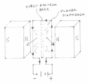 Notice now that the motor stator has both north magnetic poles facing inwards toward the armature, which is now represented by a planar loudspeaker diaphragm. The center longitudinal portion of the planar diaphragm has been affixed to a raised portion of the stator, so there will be an even portion of both magnets exposed both above and below the plane of the diaphragm on both sides. If the diaphragm is made of sufficiently compliant material, it may also serve as its own suspension at the fulcrum area, as well. However, if the diaphragm is rigid, suspension may be applied at this fulcrum area to facilitate ample movement of the diaphragm.
Also notice the absence of the split-ring commutator and brushes, which indicates that current will continue to flow in the same direction at all times. The resulting movement of both the left and right portions of the diaphragm is now directed outwards toward you, the viewer. Bingo! This is now more like the characteristics of a loudspeaker as we know it.
But how do we know in principle how to explain the movement of motors, which is what a loudspeaker essentially is? Well, we could derive that experimentally, which is what I did to confirm my findings. Or could we use Fleming’s left-hand motor rule to explain my loudspeaker’s movement? And who is this guy? Is this Ian Fleming? No, I’m afraid not. There are no James Bond spy novels associated with this guy. This is John Ambrose Fleming, who devised a set of mnemonics to illustrate the direction of motion in a motor, which is the left-hand motor rule, and also the direction of current in a generator, which is represented by his right-hand generator rule.
The left-hand motor rule is shown in Figure 3, and you can see the three vectors, F, B, and I, making it easier to remember. There are also a whole slew of other mnemonics that are used, but they are all just a variation of this particular one. Some even use the opposite hand, which is equivalent only since some of the vectors represented by the fingers and thumb have been shifted around to compensate for the use of the other hand. In this particular one I’m using, for the left hand, the thumb, represented by F, is the force, or the direction of movement. This is the unknown vector we’re looking for in this case–the direction of rotation of the motor armature. The forefinger, represented by B, is the magnetic flux density, the direction from the north pole to the south pole of the magnets. Also note that this is for an external magnetic field traversing the current-carrying conductor, not to be confused with the intrinsic magnetic field generated by the current itself within the conductor. The direction of current flow, I, is indicated by the, ahem, middle finger. Also note that this is conventional current flow as used by engineers, which is plus to minus. Physicists should not be reading this since they use electron flow, which is minus to plus. I’m just kidding about the physicists though. They are actually considered to be essentially more correct in their assessment of current flow, so they are more than welcome to read this material.
Figure 3
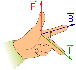
F= Direction of Mechanical Force
B = Magnetic Flux Density from N to S Pole
I = Direction of Current from + to –
So what do we have here? Take a look back to Figure 1 and study the motor layout, and contort your fingers of your left hand appropriately as shown in Figure 3 to indicate the three vectors. Voila! Indeed, what a smart guy he was. And to think it can be used without fail to determine the resulting movement of all motors. Or can it?
Now, anyone who knows me knows that I tend to stay out of the limelight. Yes, I was that kid in school who sat in the middle of the classroom, hoping to be unnoticed among all the others, and never meeting the teacher’s eye when a question was asked. All the time I was thinking, “Don’t call on me. Please don’t call on me.” And this, of course, is precisely what called attention to me. Anyway, what I’m stating here is rather controversial, as it deviates somewhat from the firmly-entrenched rules we have always used in determining the motion of motors.
Once again, prepare your left hand and contort your fingers as necessary. Now study Figure 2 where I have illustrated the diaphragm movement I have confirmed experimentally. Of course, I have taken the right magnet and reversed it so that the two north poles of both magnets now face each other. But even though I’ve removed the split-ring commutator and brushes, you would agree that at least the left portion of the diaphragm should still move towards you, the viewer, shouldn’t it? After all, this is equivalent to the first revolution of a simple DC motor, so the direction of current has not changed yet, and it won’t since I’ve removed the commutator and brushes. However, now the closest north to south magnetic poles are located on each respective magnet, and if you use Fleming’s left-hand motor rule to determine the direction of the resulting force, you will find it to be reversed from the true observed movement. How do we reconcile this anomaly? I first observed this phenomenon around 2005 or earlier, but largely attributed my experimental results to not fully understanding the semantics of the vector assignments. I still realize this is entirely possible, but my interpretation of the observed results is shown below. The results are consistently repeatable, so that’s all that really matters.
Consider a simpler example of a motor, the true ribbon loudspeaker, an audiophile favorite. This is shown in Figure 4:
Figure 4
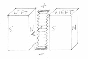
Disregard the fact that there is no impedance-matching transformer connected to the ribbon to facilitate use with an ordinary amplifier, or for that matter, that it lacks a suitable high-pass filter to prevent damage to the ribbon. Again, you will find that using Fleming’s left hand motor rule from Figure 3 yields the correct experimental results. I actually urge you to try this experiment with an old partially run-down battery if you are interested. At the very least do it with your children, if you have any, to get them interested in science and technology. After all, look what science has done for us! Well, global warming and the atomic bomb just came to mind, so never mind. Anyway, just use a piece of aluminum foil as the conductor, perhaps suspended between two blocks of wood or something, with the middle portion of the foil placed between two bar magnets to roughly approximate the configuration shown in Figure 4. Of course, you will need to keep the magnets separated, so you may want to stick these to some flat steel bar stock with adequate spacing to keep the magnets from colliding. This can actually be quite dangerous, so please wear protective eyewear at a minimum.
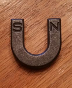
But then how do you know which pole is which on each magnet? Well, you could use one of these, a magnetic pole tester:

I doubt if you have one of those though. You could use the old standby–a magnet whose poles have already been marked, but just remember, opposite poles attract, and like-poles repel.
Or you could use a compass, but also remember that the north pole of a compass actually points toward the south pole of the earth’s magnetic field. Hence, the same thing holds true for an actual magnet–the north pole of the compass will be attracted to the south pole of the magnet. If you have neither item, simply use Fleming’s left-hand motor rule to determine each magnet’s poles. Trust me–it does work as advertised in this instance. As shown in Figure 4, if the resulting force is directed outwards toward the viewer, then you know the layout of the magnets is as shown, but if the force is directed away from you, the viewer, the magnet layout has been reversed: a N/S layout for the left magnet, and a N/S layout for the right magnet.
So now that you’ve completed this experiment (sure), remove the left magnet. Now only the right magnet remains, along with the ribbon foil conductor as shown in Figure 5:
Figure 5
When you connect the battery to the foil, what do you think happens? If you guessed that the foil’s movement is still toward you, the viewer, as in the previous example with the magnets on both sides of the foil, you would have guessed correctly. Admittedly, there is also a torsional movement of the foil as well, due to the fact that the magnet is exerting an uneven force on the foil, the current-carrying conductor with its own intrinsic magnetic field, which is created simply by passing current through it. And if you apply Fleming’s left-hand motor rule to this example, you will find that the actual result is reversed from the projected result as far as motion of the foil is concerned. After all, the only magnetic poles left now are the ones on the single magnet itself, so by pointing your forefinger from the north to south direction on the single magnet, signifying magnetic flux B, the resulting force on the foil, as indicated by your thumb, is reversed. You can’t say there is an imaginary magnet on the opposite side, along with its imaginary north pole facing the real magnet, can you? And you do agree there are still external magnetic lines of force traversing the conductor, don’t you? Otherwise, there would be no deflection of the foil when a current is passed through the conductor. Well, now if you use your right hand and use the same vector designations for each finger and thumb noted as in the left-hand rule, you will find you get the correct results.
I’m sure it comes as no great surprise that similarly, when only the right magnet is removed, the force on the foil is still directed outwards toward you, the viewer, when current is applied to the foil again. This is depicted in Figure 6:
Figure 6 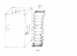
Also, once again, this movement may be described by a right-hand rule using the same vectors as used in Fleming’s left hand rule. Yawn. Well, I thought this was a primer on a different type of loudspeaker! Well, maybe it is. What if you bonded the ribbon as shown in Figure 6 to a flexible carrier, and in turn, this carrier was affixed to a fulcrum point opposite the magnet side of the foil, along with an impedance-matching transformer connected to the ribbon ends? It would be a unique pseudo-ribbon, and it is actually the basis of my woofer construction, minus the transformer. Well, minus the foil too, for that matter. I use wire.
But my point about Fleming’s left-hand motor rule is this: It is very useful in describing the force on a current-carrying conductor in specific circumstances, specifically when the conductor is placed between two unlike poles of individual magnets or the poles of a single horseshoe-shaped magnet. Otherwise, this force is best represented by a similar right-hand rule, representing the contribution of each individual magnet to the total force on the conductor. For example, look back again at Figure 4. Using the right-hand rule, point your forefinger from the north to south pole contained within each individual magnet, not from the north pole of one magnet to the south pole of the opposite magnet. Then use the middle finger for direction of current flow from plus to minus, and you will see that the resulting force will be directed outward towards you, the viewer, as indicated by your thumb. Repeat this for the other magnet, and now you can see the contribution of each magnet to the total resulting force, which may then be depicted using Fleming’s left-hand motor rule between the opposing magnets. From what I have ascertained, this right-hand method always yields correct results in all circumstances, but Fleming’s left-hand motor rule yields correct results only in specific circumstances. Worse yet, I’ve seen countless examples scattered throughout the Internet, even in reputable academic publications, whereby it is stated, “Fleming’s left-hand motor rule is used to describe the force on a current-carrying conductor in a magnetic field.” In my opinion, this article “a” denotes “any”, so this is not worded well at all, as it is simply not true in all circumstances. Maybe Mr. Fleming simply did not anticipate someone making some crummy loudspeakers that appear to violate his well-established rules. I really don’t know, and I guess it really doesn’t matter, as many of you have witnessed the loudspeaker’s correct operation. That’s all that really matters, I suppose. Maybe I’m just nitpicking.
Conversely, as you also may have guessed, Fleming’s right-hand rule for generators seems to suffer a similar fate with the use of a single magnet as the source of magnetic flux. I first attempted to measure the direction of current flow by deflecting a piece of aluminum foil in both directions adjacent to a magnet’s single pole, but the results were inconclusive since the resulting output was so low, barely measureable with a DMM set to the millivolts scale. Then I realized since I had already marked the electrical polarity on the terminals of my planar loudspeaker woofers by establishing polarity with a 1 1/2 volt cell, I could use the woofer’s greater electrical output to determine the direction of current flow when the diaphragm was deflected either forward or backward. This is because the voice coils are adjacent to only one magnet’s pole per woofer. Sure enough, current direction was opposite that indicated by Fleming’s right-hand generator rule, and was best described by a similar left-hand rule, but using the same vectors as outlined in the right-hand rule. This was apparent as I deflected the diaphragm forward and observed a positive DC voltage, whereas a reversed deflection resulted in a negative DC voltage when the test leads were connected with the correct polarity. Of course, this would only make sense with the knowledge gained from working with the single magnets. But I know–boring stuff!
